LCD
In this lesson, you will learn how to wire up and use an alphanumeric LCD display
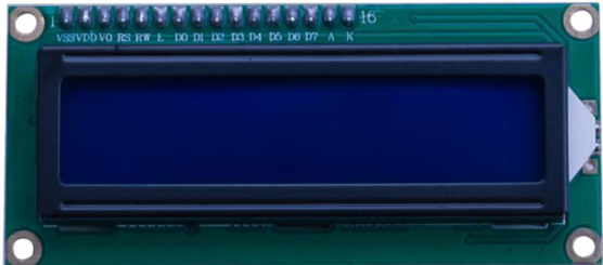
The display has an LED backlight and can display two rows with up to 16 characters on each row. You can see the rectangles for each character on the display and the pixels that make up each character. The display is just white on blue and is intended for showing text. In this lesson, we will run the Arduino example program for the LCD library

Component Required:
1 x Uno R3
1 x LCD1602 module
1 x Potentiometer (10k)
1 x 830 tie-points Breadboard
16 x M-M wires (Male to Male jumper wires)
LCD1602:
Introduction to the pins of LCD1602:
VSS: A pin that connects to ground
VDD: A pin that connects to a +5V power supply
VO: A pin that adjust the contrast of LCD1602
RS: A register select pin that controls where in the LCD’s memory you are writing data to. You can select either the data register, which holds what goes on the screen, or an instruction register, which is where the LCD’s controller looks for instructions on what to do next.
R/W: A Read/Write pin that selects reading mode or writing mode
E: An enabling pin that, when supplied with low-level energy, causes the LDC module to execute relevant instructions.
D0-D7:Pins that read and write data
A and K: Pins that control the LED backlight
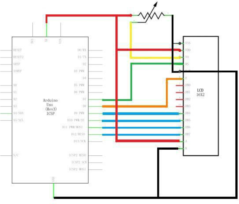
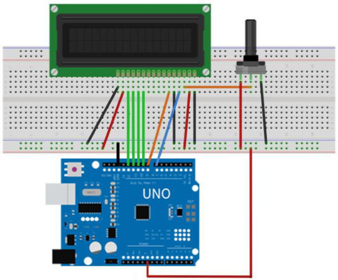
Connection Diagram:

Wiring schematic:

Physical Wiring Diagram:

The LCD display needs six Arduino pins, all set to be digital outputs. It also needs 5V and GND connections. There are a number of connections to be made. Lining up the display with the top of the breadboard helps to identify its pins without too much counting, especially if the breadboard has its rows numbered with row 1 as the top row of the board. Do not forget, the long yellow lead that links the slider of the pot to pin 3 of the display. The 'pot' is used to control the contrast of the display. You may find that your display is supplied without header pins attached to it. If so, follow the instructions in the next section.
Code
After wiring, you need to install the relevant library file <LiquidCrystal.h> listed below:
Code Explained
The first thing of note in the sketch is the line:
This tells Arduino that we wish to use the Liquid Crystal library.
Next we have the line that we had to modify. This defines which pins of the Arduino are to be connected to which pins of the display.
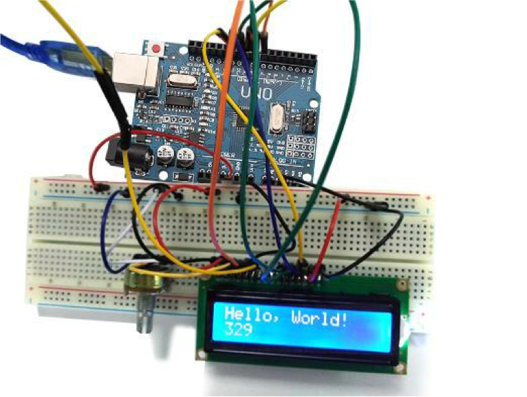
After uploading this code, make sure the backlight is lit up, and adjust the potentiometer all the way around until you see the text message.
In the 'setup' function, we have two commands:
The first tells the Liquid Crystal library how many columns and rows the display has.
The second line displays the message that we see on the first line of the screen.
In the 'loop' function, we also have two commands:
The first sets the cursor position (where the next text will appear) to column 0 & row 1. Both column and row numbers start at 0 rather than 1. The second line displays the number of milliseconds since the Arduino was reset.
Last updated